Keypad ⌨️
Components.
- Arduino UNO (2)
- LCD OLED I2C 128 x 64 (1)
- LCD 16 x 2 SPI (1)
- Buttons (4)
- Module Bluetooh HC - 06 (1)
- Module Bluetooh HC - 05 (1)
- Transformer 5v (2)
- Buzzer (1)
Square 1:1 Component Table.
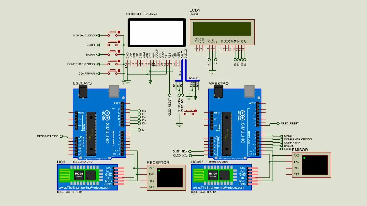
General diagram.
Keypad diagram.
Progress
At the beginning we program the push buttons to send a word written by the user to the serial port. For this the user has to navigate through the array abc through the letter by letter pushbuttons until you find the one you want and when you finish sending it. The teacher who will be in charge of sending for serial port this data, so that, when entering the “finish word” button, only the loaded word is sent. As shown in “figure 10 ”.
Circuit with push buttons and serial display.
Once we have the circuit, to check that it works, we enter a certain number of letters to be aware of how it works. The letter “ñ” is not in our language, but we will correct this later. In this case we use the serial to check that we do not have errors in the code since it may happen that due to connection errors we take much longer in finding the error that if we only use the serial port. In addition, later it will help us since we know what it has to show on the display and it doesn’t have to show in case of errors.
Serial display.
We changed the pull down buttons that we were using for pull up buttons, since it allowed us to use the internal resistors of the Arduino and save on components (which in this case are not necessary) and the circuit is more compact.
Diagram pushbutton Pull Up.
In order to use the buttons we need to change the configuration of the current pins, since they were in pull configuration down. To change them we have to configure the modes in which Arduino reads the pins, both input and output. In order for us to use it, we have to have the pins in the IPUT_PULLUP mode since it allows us to always have 5v at the output. We add the HC-06 and HC-05 Bluetooth Module. In the case that we only have these modules in simulation we have to create two virtual ports so that proteus allows us to read both modules. We use the program to simulate these pins. (The libraries that we use for the modules, we leave them at the end of the report).
Pins simulator.
Once we have finished assembling the code and being able to configure all the necessary pins to be able to use the bluetooh modules in proteus, we arrange the connections of both the pushbuttons and the modules to be able to use it from both serial screens. We have both the receiver and the sender. We have an image that shows us how it works on both serial screens.
Circuit with printed pushbuttons.
Circuit with serial ports in simulation.
We have the circuit working and showing what it would look like in the series when a complete word is sent. We use the script as symbol for “space”. Once the word is sent it restarts. In the button code “DOWN”, instead of use a “delay ()” which is a blocking function, we use a counter, the number in counterB is 10000 since the button was slower than the path of the same one and returned to execute another letter. That is why that is the minimum value.
Pushbutton Configuration.
Arduino master
On the part of the master Arduino circuit, it is shown how it looks after entering the oled that we will use as interface and menu for the client. The interface is displayed on the LCD and as we press the switches, we can move between the menu options that we have loaded previously.
Complete assembly of the Arduino master.
Master Arduino Printed Circuit.
We have the printed circuit in case we are going to mount it or send the pcb board to be made. We also modeled the board in 3D so that the user who builds the circuit has a broader view of how it would look once completed.
Back of the plate.
Front of the plate.
We had to use a Jumper since we were not presented with another way to complete it.
Arduino slave flow chart.
Arduino Slave.
Once we have the master we proceed to install and program the slave Arduino, it will serve as a receiver through which the master Arduino sends a word written by the user and shows on the lcd that we have this same Arduino connected and that it can alert that a phrase arrived.
Assemble the slave Arduino.
The Arduino slave PCB is shown in the image, we have both the Arduino and the 16x2 display.
Arduino Slave PCB.
3d printed circuit of the Arduino slave.
To have a vision of how the circuit would be already assembled, we proceed to show the circuit in 3d.
printed back
front printed
Simulation Proteus.
We have images of what is the simulation in proteus by the Arduino slave, but in this one the option to confirm the requested option was already chosen.
Oled confirming option
The first thing to do is save option 1 since we have an array in which we are saving the words that we are writing. If we enter again to our circuit, we would already have the options loaded by the eeprom. When we load the options.
Oled selec slot.
Here, regardless of the option chosen, we can already show it both through the display and through the serial.
Emitter and Receiver Terminals.
It shows how the message sent through the master Arduino would look on the slave Arduino
LCD Receptor.
Once the display of the slave Arduino is finished, we proceed to connect the main display to the master Arduino, with this we will control the main menu where our client can insert the options and then save them, with an interface that shows the name of the school .
Final Assembly of the Project.
Conclusion
In the first part of the work we dedicated ourselves to the basic assembly of the Arduino master (the buttons plus the serial monitors), in this same we program so that the customer can enter words at his convenience and send them to the menu principal. On the receiver side, we have a slave Arduino which is in charge to load the phrase that was loaded by the master Arduino and send it to the second 16x2 display, this will show the message sent by the client. At the end of the project, we were able to finish with all the objectives already set that meets all the necessary requirements, for the operation basic circuit.
Upgrades
- Make an api to control the buttons
- Increase key reading speed
- Polishing the user interface
- Have power for both Arduinos